Neutral Atom Array Experiment
Since 2023, I have had the privilege of being part of the Semeghini lab, which aims to build a dual-species Rubidium-Ytterbium neutral atom array with continuous reloading. This experience has been instrumental in shaping my understanding of the connection between physics and computation; it helped me gain:
- In-depth knowledge of experimental control systems: whole-stack knowledge of the design, compilation, and (asynchronous) physical execution of experimental sequences. Familiarity with national-instrument systems.
- Experimental skills: designing and building optics; E&M simulation.
- High-level insight into system integration in the neutral atom platform: this include the organization and main components of a neutral atom array, as well as how basic physical components are assembled and classically controlled to facilitate (quantum) computation.
a. Experimental Control System (June - Dec, 2023)
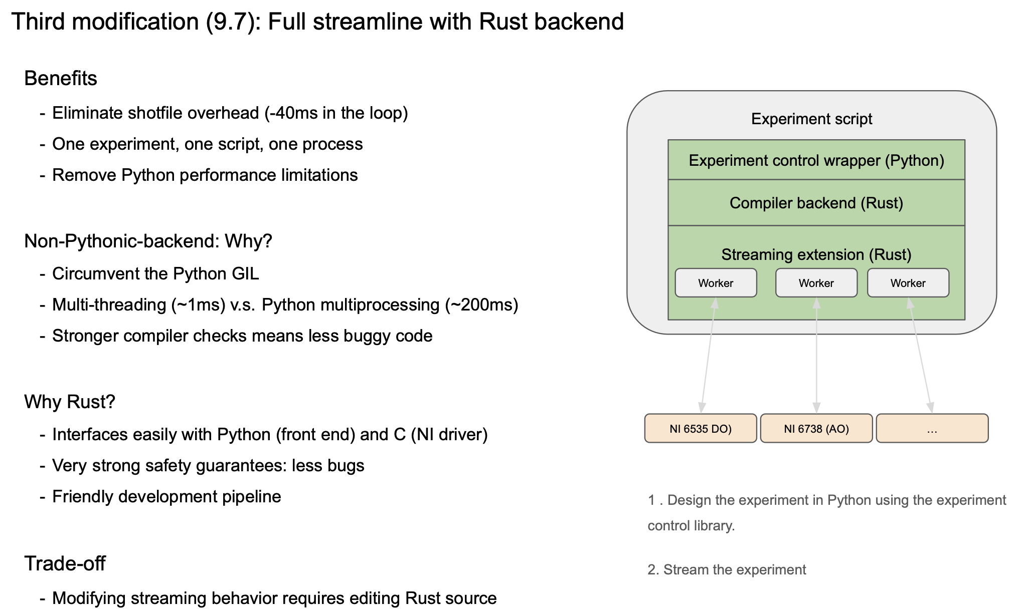
Spearheaded the development of an experimental control system in collaboration with Pavel Stroganov; it is designed to meet the unique demands of neutral atom array experiments. Highlights:
- Addresses key challenges such as streaming signal generation for long-duration, high-resolution experiments and intuitive multi-device integration.
- An experiment-level abstraction for National Instrument (NI) hardware, enabling high-level management of multiple devices and synchronized experimental tasks.
- Leverages a Rust-based backend for performance and safety, integrated with Python for ease of use.
- See the repository, or the experiment execution and compiler documentations for details.
The control system is currently under active use and maintainance in the Semeghini Lab and Atom Array 2 group at Harvard, where it facilitates the design and execution of complex experimental sequences. See the the experimental control report slides for more details on the improvements relative to Labscript and our design choices.
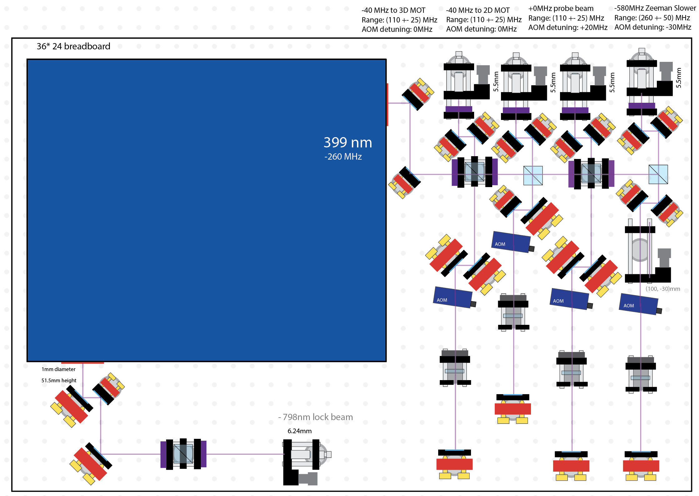
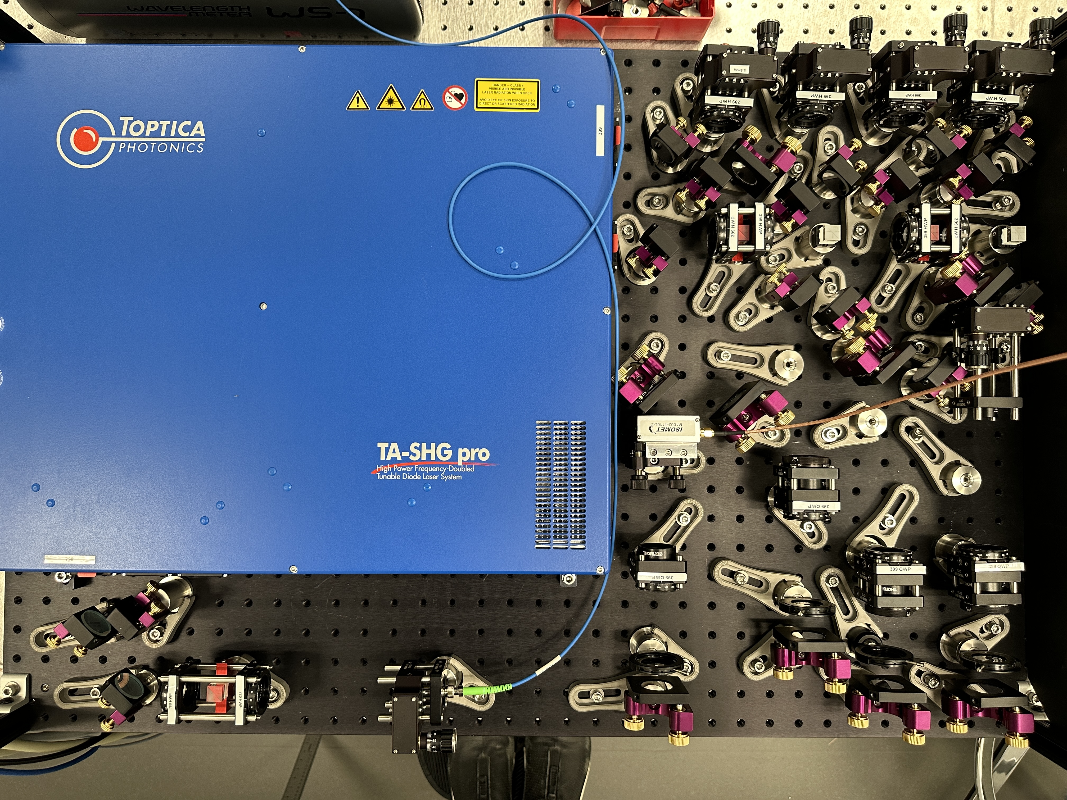
b. AOM double-pass with Toptica 399nm laser (May - June, 2024)
The goal of this project is to extract four separately-detuned beams from the Toptica TA-SHG pro for 2D MOT cooling (-40MHz), 3D MOT cooling (-40MHz), probing (+0MHz), and Zeeman slowing (-580MHz), respectively. My main takeaways:
- Optical circuit design: familiarity with optical components, polarization, fiber coupling (key equation \(f=\pi \omega D/4\lambda\), also see reference), and AOM.
- AOM double-pass: designing, identifying relevant parts, and implementing a cat’s eye double-pass configuration.
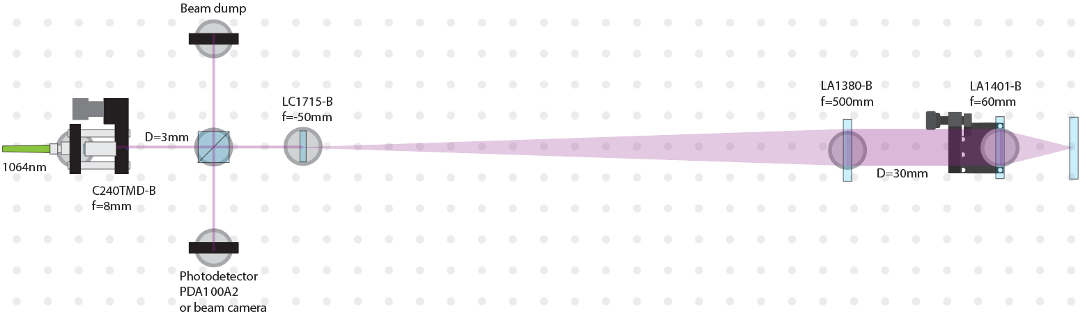
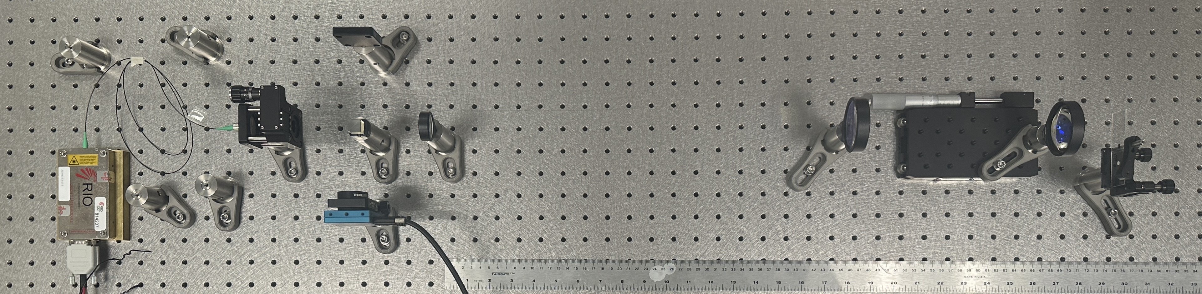
c. Precision Measurement with 1064nm laser (Sep - Oct, 2024)
This project focuses on accurately measuring the thickness of the glass cell panes along the critical optical path of the tweezer setup. The measurement is performed by directing a tightly focused Gaussian beam (Rayleigh range ∼1μm) at the sample and identifying the focal plane by detecting the maximum intensity and coherence of the reflected light. Key takeaways:
- Optical design: Calculating Gaussian beam parameters to achieve a ≈1μm deep focal spot using a 1064nm laser source and selecting appropriate components from Thorlabs.
- Setup construction: Involved fiber out-coupling, alignment of a 3cm-diameter beam, and using a beam profiling camera.
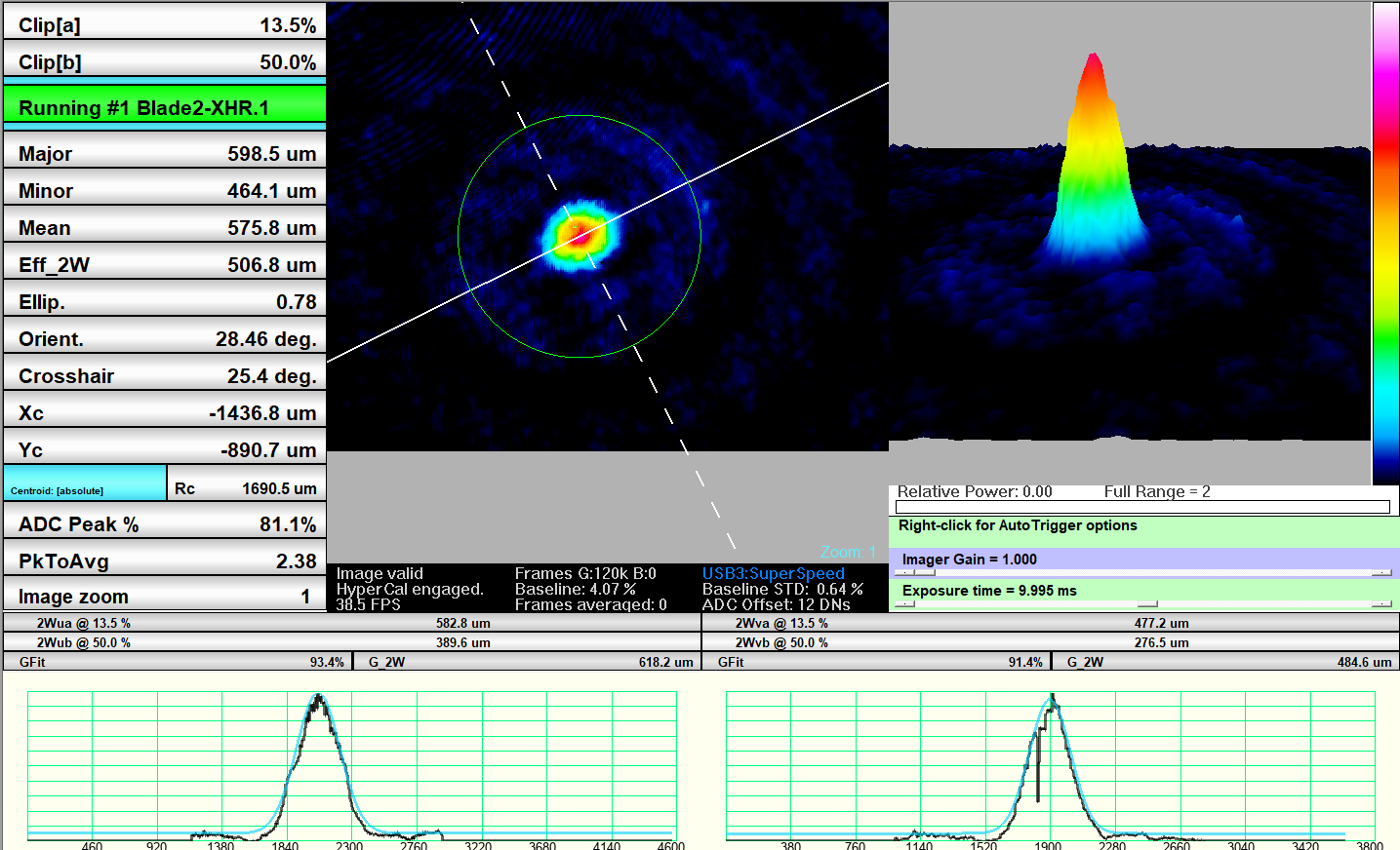
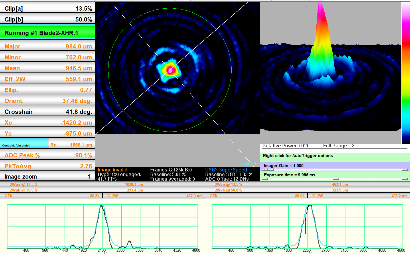
The video below records the reflected pattern during translation stage movement: the two Gaussian-like reflection patterns (approximately at 0:08 and 0:17 in the video) correspond to reflections from the first and second surfaces of the glass sample, respectively. The distinct reflection patterns obtained from the first and second surfaces of the test sample indicate successful identification of multiple interfaces.
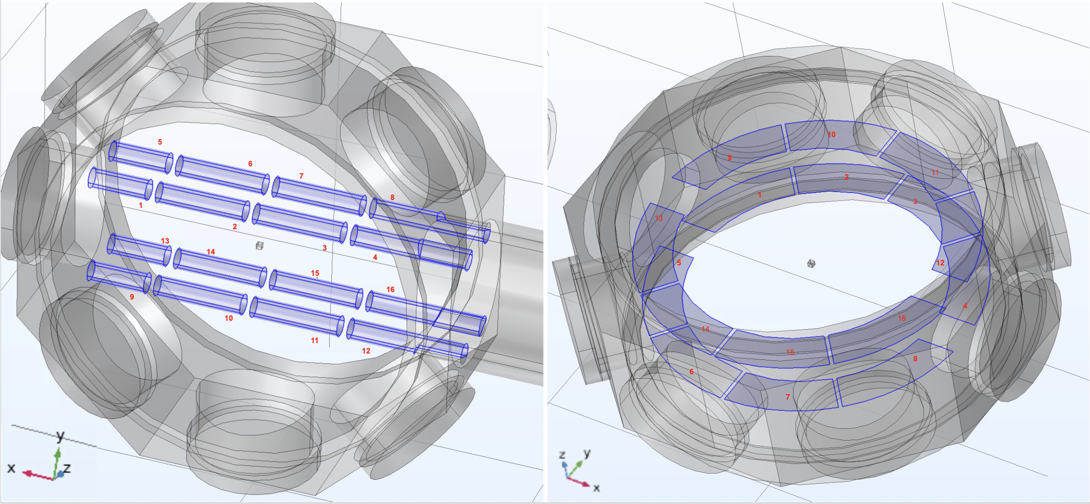
d. COMSOL simulation for electrode design (June, 2023)
This simulation project aims to assess the efficacy of cylindrical or disc-shaped electrodes to help offset stray DC fields, which cause Stark shifts. Key takeaways:
- DC Electrical field simulation using COMSOL (course link), and denoise-capability estimation using least-squares.
- Simulation (see slides for details) reveals that the 16-pole cylinder is almost the same as the 8-pole cylinder; this helped inform our final electrode design below.